 |
| Minimum Order Quantity: | 100 |
|---|---|
| Packaging Details: | Original packing |
| Delivery Time: | 1-12 weeks |
| Payment Terms: | T/T |
| Usage: | Current | Coil Number: | Autotransformer |
|---|---|---|---|
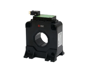
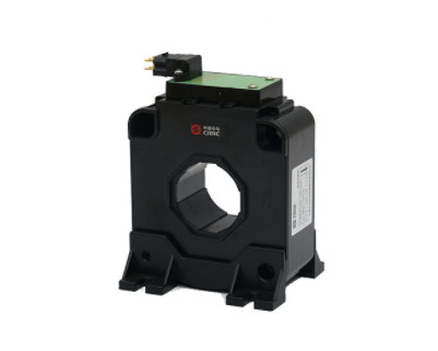
| Output: | Analog Sensor | Product Name: | Max Dc Input 1500A Split Core Hall Effect Current Sensor |
| Accuracy: | 0.5 | Operating Temperature: | -20℃to 70℃ |
| Input Current: | 15A | Frequency: | 50/60Hz |
| Highlight: | Split Core Hall Effect Current Sensor,1500A Hall Effect Current Sensor,Hall Current Sensor GB/T 25119 |
||
product manual
NACL.1000Q-S3/N magnetic balance Hall current sensor is suitable for accurate measurement of AC, DC and pulse current isolation. The primary side and the secondary side are completely insulated during measurement.
| product advantages | Applications | Reference standard |
| High precision | AC Inverter AC | GB/T 25119-2010 EN50155 |
| Good linearity | Converter/Inverter | |
| Low temperature drift | UPS/SVG | |
| Broadband | ||
| Quick response |
| Main electrical parameters (@±IPN, TA = 25℃) |
|
| Rated measuring current IPN | 1000 |
| Measuring range IPM | ±2400 |
| Power supply voltage VC | DC±(15~24)×(1±5%)V |
| Current consumption IC (@±24V) | ≤±30mA+ISN |
| Rated measurement output ISN | 200mA |
| Turns ratio | 1:5000 |
| Load resistance RM | @±15V,±1000A:0~15Ω @±15V,±1200A:0~7Ω @±24V,±1000A:0~50Ω @±24V,±2000A:0~7Ω |
| Accuracy-dynamic parameters | |
| Basic error δi(@IPN,TA=25℃) (@IPN,TA=-40℃~+85℃) |
≤±0.4% ≤±1% |
| Linearity δL (@IPN,TA=25℃) |
≤±0.1% |
| Zero output current IO (@IP=0, TA = 25℃) |
≤±0.5mA |
| Zero temperature drift IOT (TA=-40℃~+85℃) |
≤±1.0mA |
| Response time TR (90% of IPN&di/dt> 50 A/µS) |
≤1µS |
| General data | |
| Working temperature Ta | -40~+85℃ |
| Storage temperature Ts | -45~+90℃ |
| Weight m | ≤900g |
| Insulation withstand voltage | |
| Withstand voltage | 13.4kV |
NACL.1000Q-S3/N current sensor outline drawing
Electrical connections
| Mechanical characteristics |
| 1. Sensor installation aperture: 4×φ5.5mm |
| 2. Recommended use: M5 bolt fixation |
| 3. Installation and fixing torque: 3.5N·m |
| 4. Through hole on the original side: φ42mm |
| 5. Secondary side electrical connection: M5 bolt (or 6.3×0.8 plug reed) |
| Remarks |
|
1. When the measured current direction is consistent with the direction marked on the sensor, the sensor output ISN is positive. 2. The secondary side connection line of the product is preferably a shielded line, and the shielding layer is close to the product end and the connection line can be connected to the case, and the negative power supply or power supply 0V. 3. The verticality requirement of the mounting screw hole of the power sensor: it must be level 8 or above in the national standard (or below 0.06). 4. Flatness requirements for the installation surface of the power sensor: (a). The flatness of the large plane installation is level 11 or above in the national standard (or the plane fluctuation is less than 0.25mm); (b). When the installation surface is designed with a small round boss, the flatness shall be level 12 or above in the national standard (or the plane fluctuation is less than 0.5mm); 5. No tolerance ±0.5mm;
|
Contact Person: Miss. Elaine
Tel: +86 18150151931
Fax: 86-592-2611505